
The baby 8 finished product.


Guts

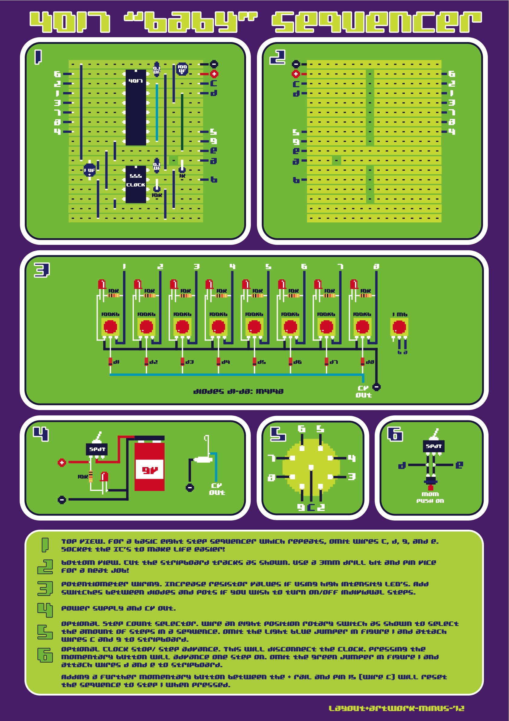
My layout design

This is the simple baby 8 sequencer. Based around the 4017 chip, and clocked with a 555 timer. 0-5v CV output, 1-8 step selector switch, and a rate control. Original circuit can be found here. My build is a variation of this design with an added voltage regulator.
Can you explain the wiring, where 1-9, and c go?
ReplyDeleteYep, The 'C' represents the center pin on a 8 position rotary switch. '1' goes to the first pot, '2-8' go to the rotary switch and their respective pots, and '9' also goes to the rotary switch.
ReplyDeleteThis file below has the wiring diagramed mostly:
http://electro-music.com/forum/phpbb-files/baby_sequencer_v1_128.jpg
You can also look at the guts shot of my build to help you out. The wiring is definitely the most confusing part of the project.
Also, also you can omit the rotary switch and just solder a bridge between '9' and 'C', but the step selector is a really nice feature.
Hi, 2 wires from every one of the 7 rotary pins go to the corresponding vero hole and to the corresponding pot pin, am I right?
ReplyDeletethank you
Hi, I think you have it right. The wiring is kinda tricky. Hopefully the guts picture can help you out.
DeleteWhat purpose does the trimpot serve?
ReplyDeleteThe trim pot is a simple voltage regulator. I added that so I could get a perfect 5V output.
DeleteHey, nice build! But how / with what do you power it?
ReplyDeleteHi, It's powered by a 9V DC power supply (like a guitar pedal PSU). Or you could power it with a 9V battery if you attach a battery terminal.
ReplyDelete