Saturday, October 29, 2016

HV857 - Tiny EL Lamp driver (QY10 backlight)


This is a neat little electroluminescent (EL) driver board.  It uses the HV857 lamp driver IC and only 7 external parts.  The PCB board is only 12mm square, and it runs off of 1.8-5v DC.  It would run fine of a couple batteries.  It's not the brightest and don't expect it to light up a long strip of EL tape or anything. It works good for smaller LCD backlights and such.

PC board layout if you want to make your own!  Also, here's a mouser parts list if anyone is interested.  Also also, here's the eagle files I made for this project.


Guts of my QY10 with the EL board installed

QY10 backlight action.  Yay!

Sunday, August 2, 2015

Fostex Mixer/Reel-to-Reel VU meter fix


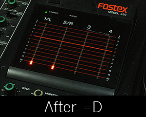
I recently picked up a Fostex-R8 eight track reel-to-reel recorder, and then snagged one of these Fostex 450 mixers to go with it.  The mixer worked great except for the LED VU meters.  most of the LED's appeared dead like in the above 'before' GIF.  Lurking around the internet, in forums, and message boards,  I came to realize this is a common problem with these machines.  Luckily my R8's LED's are all working fine.  I believe the VU meter boards are all very similar between the various Fostex mixers and reel-to-reels.  So, this little tutorial might help out anyone with one or more of these machines.  With patience and a steady hand, you too can have all new fully functional VU meters!

 This is what the LED meter looks like when you get is out of the mixer.  It's held in with plastic clips, that need to be gently pushed apart to free the board.  That black button on the left is the LED driver chip.  There is no way to replace that, so if it gets damaged your out of luck.  On top of the LED's is a white plastic piece to house the LEDs and diffuse the light into nice looking rectangles.


I had to use a blade to get the plastic piece off.  The piece has four small dowels that fit through the PCB and bevel out to hold it on.  I just cut the bevel off to release it.  Now I can see the teeny tiny LED's.

 Here's a closeup of the fragile micro LED's.  Like .1mm squares with a single hair wire attached to the top of them.  No wonder these things fail!  With a small point soldering Iron I removed all the old diodes.

 And here's the replacements!  Modern 0603 surface mount LED's.  These are similar in design except they are encased in an epoxy or resin.  This protects the hair wire from braking.  If you've ever solder SMD components you probably know extra Flux is important and very helpful.  I used flux to help tin the trace pads and hold the LED's in place while soldering.

Here's one finished board.  The plastic diffuser piece fits right back over the new LED's, and the PCB snaps right back into place.  I'm not going to lie, it's a tedious job, but once your done you'll have fully functional beautiful bright new VU meters.  They should last a good long while too.  I hope this helps some people out!  Feel free to contact me if you have any questions.

cheers,


Addendum:
If anyone has dead LED's and isn't comfortable doing this procedure themselves I might offer a repair service in the future.  Ideally you'd be able to remove the VU boards yourself, and mail them to me instead of the whole machine.  I haven't worked out prices, but it would be reasonable (cost of materials and time).

Saturday, May 30, 2015

Noise Toaster

This is just a show off post of my noise toaster.  If you don't know, the noise toaster is a simple-ish, lofi synth, noise maker, designed by Ray Wilson.  You can find all the info needed to build your own over at MFOS.  This thing is really versatile and capable of producing all types of lofi synthy goodness.  It can run on a 9v battery and has a built-in amp and speaker, for on-the-go sonic exploration.  I highly recommend this project to anyone into DIY noise makers! 


Added the mods suggested on Rays site.  Both useful additions!


Added a tiny little laptop speaker cuz why not.


And here is a track I made that features the noise toaster.  All the bleeps and blips running through the whole beat is all toaster madness.

Saturday, April 25, 2015

Echo-Matic (DIY Tape Delay)


I designed my echo-matic panel in the style of the Univox EC model tape delays


Here's my setup:  1/4" instrument input and output, and RCA I/O's to connect to the tape recorder.  I'm using a Marantz PMD221.  I modified this machine slightly by adding a second pitch control.  That's what that little knob at the top right corner of the marantz unit is.  This knob adjusts the pitch drastically for slower delay effects.


This surprisingly simple circuit turns any 3 head tape recorder into an awesome sounding tape delay machine.  The tape recorder has to be a three head unit (erase head, record head, and play head) for it to work.  This type of recorder will have a button or switch that allows you to listen to the source audio, or what has just been recorded to the tape.  The small gap between the record head and the play head creates the delay effect.  I'm a novice when it comes to circuit design, but the schematic just looks like four buffers and some pots to mix the different signals together.

Here's the original literature for the echo-matic:

And here's a layout I redrew from the above article.  It's 600dpi and the image is reversed for photosensitive boards.

Echo-Matic PCB Layout PDF Version For easy printing!


Gutz! :]


Per request:

Here's some additional photos and info about the mod I made on my PMD221.


The Pitch knob had a 1.2K resistor in series with it.  All I did was desolder one pin of that resistor and replace it with a 1k pot.  In the picture above you can see the wires running from that circuit board to the 1K pot attached to the battery compartment door.  With this mod, I can get the delay times to somewhere around 500ms before the tape drive stalls out and stops.


A closeup of the solder points


I don't run this unit on batteries so sticking the pot in the battery compartment seemed like the best place to for it.

Sunday, February 1, 2015

Paia 2700/4700 Clone Project coming soon!


So like at least a year or so ago I started this Project and never put the finishing touches on it.  Really it's just the panel graphics that I never got around to doing.  It's a clone of the old Paia synth modules.  The 2720 keyboard and some of the 4700 modules too.  Everything was hand fabricated and all the circuits built on stripboards.  In future posts I'll break down the modules, take pictures, and share the veroboard layouts.

Stay tuned!

Monday, December 8, 2014

Monday, June 16, 2014

EPFM (Electronic Projects for musicians) Build notes and layouts


Here's a dump of layouts, pics and info about my EPFM modular build.  I didn't include any of the schematics in this post.  They are easy to find if you google them.  PDF versions of the EPFM book is easy to find too.  If you want to build these effect you'll need those resources.  The book has circuit descriptions and will make pot wiring easier.


RING MODULATOR


 gutz


Craig Anderton's Ring mod.  This ring mod sounds good.  It has a little bit of carrier wave bleed thru like most ring mods do.  Nothing too distracting thou.  I added a tone switch and a pitch switch to this circuit.  I think they were both suggested mods in the EPFM book.


SUPER TONE CONTROL


 guts


Envelope switch connections


The super tone control is awesome!  A really useful and versatile tone circuit.  Three band control with frequency and resonance!  Very synth-like.  I goes from super low, boomy bass tones to whisper twinkly high tones, and everything in-between.  Prolly the best circuit of the lot.  I didn't have to make a layout for this one because tagboardeffects already has one made up.  I did remove the charge pump because I have a +/-9v supply running into it.


PHASE SHIFTER


gutzy


This phaser sounds pretty cool but I wouldn't call it lush or anything.  Compared to my Ross 8 stage phaser,  well, it doesn't compare.  It is capable of other interesting high resonant modulation type sounds though.  This is one of the more complex circuits to build.  It has the most parts and uses four vactrols or opto couplers.  It calls for CLM6000's in the book.  These are non existent these days.  Some people have luck building there own vactrols with LED's & Photocell's.  I bought some opto couplers from electronics goldmine.  You can buy them individually or get a lot of untested ones.  I went for the lot and hand picked ones with similar resistance values.  


ENVELOPE  FOLLOWER


Guts


This is the envelope follower circuit found near the back of the book.  This is like an add on that works in conjunction with the other effects.  This circuit also uses the opto couplers mentioned in the Phase shifter text.  If you go back and look at the pictures of the Tone control front panel , and the front panel of the Phase shifter, you'll see the envelope switches.  These switches activate the envelope for these effects.  When activated on the tone control it acts like an auto filter type effect.  On the Phaser it's suppose to add a swell type effect.  The envelope works great on the tone control and not so well with the Phaser.


SPRING REVERB


 yup


This is the one effect that didn't come from the EPFM book but it is a Craig Anderton design.  I actually stripped down this circuit.  The tank I used has a long decay and a dark tone for a spring reverb.  The parts I removed seem to muffle the sound further.  The reverb still sounds kinda dark but in a neat way, I think.  


POWER SUPPLY


Some extra pics of the enclosure, reverb tank, and PSU.  The PSU is pretty much the MFOS wall wort PSU with 9v regulators.

Hope you enjoyed the pics and info.